Calculation of power electronics converters
CONTENTS
Abstract
1.Choise
of designing direction
1.1 The
review of circuit solutions
.1.1 Three-phase
rectifier with center tap
1.1.2 Three-phase
regulated rectifier with center tap (LH=¥)
.1.3 Three-phase
bridge regulated rectifier
.1.4 Non-symmetrical
scheme of three-phase bridge rectifier
.1.5 Larionov’s
scheme
1.2
The review of constructive solutions
1.2 Statement
of problem
2.Principle
of designed scheme operation
.
Calculation of rectifier working on active-inductive load
.
Construction of the device of literatureA Reference data of diodeB Reference
data of throttleC Reference data of transformer
Appendix
D Reference data of clamped
connection
rectifier electronic
converter
INTRODUCTION
Electronic apparatus are referred to
devices of a power electronics used in various systems and electric power
supply sources, which serve for conversion of electrical energy with one
parameters to electrical energy with other parameters. For example, conversion
an alternating-current to a direct one (rectifiers); a dc to ac (inverters);
alternating-current of one frequency to an alternating current of another
frequency (frequency converters); a direct voltage (current) of one value to a
direct voltage (current) of other value (a voltage (current) converters).
Electronic devices for a filtration and stabilization of current and voltage
are also referred to devices of power electronics. All set of forth-above
devices are termed as converters.
The design procedure of low power
converters differs from a design procedure of high-power converters die to
specific features of these devices, but electromagnetic processes in them have
the same character. Course designing on discipline « Bases o power electronics
» puts the purpose obtaining of practical skills in calculation of power
electronics converters explanatory note, development of designs and drawing up
of engineering specifications of converting units.
1.
CHOICE OF DESIGNING DIRECTION
1.1 The review of circuit
solutions
.1.1Three-phase rectifier with
center tap
The latter
kind of load should be considered as opposite electromotive force with
inductance. The component element of complicated schemes of three - phased
current rectifiers is a simple three - phased scheme with center tap, suggested
by Mitkevich. In this scheme dispersion of transformer windings aren’t taken
into account, that is available for small power rectifiers; also it is
considered that valves and transformer are ideal. In idealized scheme
commutation is realized instantaneously, at any time moment current is
conducted only by one valve, anode of which has the most high potential. The
durability of work of every valve is  . The rectified voltage and current
contain thrice-repeated pulsation by period.
. The rectified voltage and current
contain thrice-repeated pulsation by period.
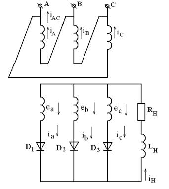 1.1 - The three-phased rectifier
with center tap by active-inductive load.
1.1 - The three-phased rectifier
with center tap by active-inductive load.
It should be mentioned that in
three-phased rectifier with center tap there is such a phenomenon as
steady-state magnetization of transformer core. It is one of the disadvantage
of usage given scheme. three-phased current rectifiers for decreasing of rectified
current alternative component there usually link up inductive smoothing filter
in a series with load, inductance of which has definite value (LH).
The work regime of such a scheme is:
ra=0, La=0,
0<LH<¥
Also let’s consider scheme of three-phased
rectifier
taking into account the next condition: ra=0, La¹0,
LH=¥
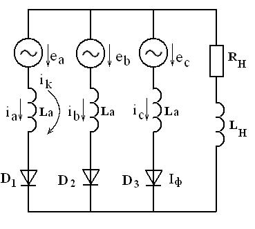 1.2 - The equivalent scheme of the three-phased rectifier
with active-inductive load
1.2 - The equivalent scheme of the three-phased rectifier
with active-inductive load
scheme is
used in case of considering dispersion inductance of transformer windings La
and LH=¥.fact,
the accurate definition of electric parameters of rectifier
is greatly complicated because of the form of current curves in secondary and
primary transformer winding that depends of angle of commutation. Consequently,
it causes some problems in calculation of rectifier
parameters.
.1.2 Three-phase regulated rectifier
with center tap(LH=¥)exist
not only non-regulated there-phased rectifiers
but also regulated there-phased rectifiers.
Usually it is used a scheme with center tap (regime when ra=0, La=0,
rnp=0).
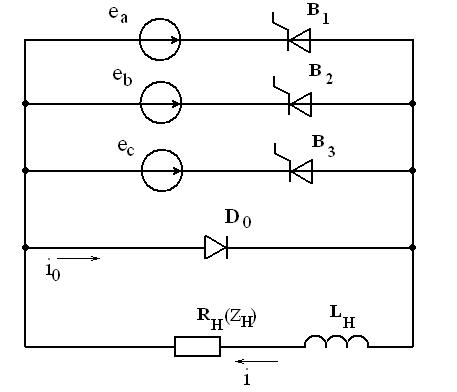 1.3 - The scheme there-phased
regulated rectifier
with center tap (LH=¥)
1.3 - The scheme there-phased
regulated rectifier
with center tap (LH=¥)
case of
active-inductive load this scheme can work in two regimes: regime of continuous
currents, when (angle of
regulation a
in there-phased rectifiers
is considered to count from the point of natural opening of values); and regime
of interrupted currents
(angle of
regulation a
in there-phased rectifiers
is considered to count from the point of natural opening of values); and regime
of interrupted currents  . The
interruptance of current in load curcuit depends not only on rate of charge of
regulation angle a,
but also on relation of load parameters RH and LH. Like
in one-phased scheme, the curve of rectified voltage on the interval a
may have the negative voltage on winding of given phase due to the accumulated
energy in magnetic field of throttle LH.deleting negative parts in
curve of rectified voltage and improving power coefficient of rectifier zero
valve D0 is involve is scheme, which shunts a load. Current through zero valve
by active-inductive load is supported due to electro motive force of load self
induction and flows by the internal of time p/6 -a.
The voltage on load at this time internal is equal to zero, and thyristors B1,
B2, B3 are closed.
. The
interruptance of current in load curcuit depends not only on rate of charge of
regulation angle a,
but also on relation of load parameters RH and LH. Like
in one-phased scheme, the curve of rectified voltage on the interval a
may have the negative voltage on winding of given phase due to the accumulated
energy in magnetic field of throttle LH.deleting negative parts in
curve of rectified voltage and improving power coefficient of rectifier zero
valve D0 is involve is scheme, which shunts a load. Current through zero valve
by active-inductive load is supported due to electro motive force of load self
induction and flows by the internal of time p/6 -a.
The voltage on load at this time internal is equal to zero, and thyristors B1,
B2, B3 are closed.
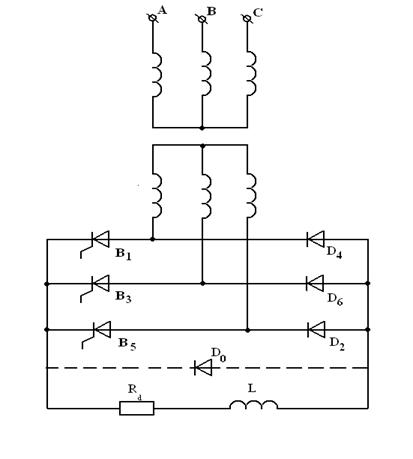
1.1.3 Three-phase bridge regulated
rectifier three-phased bridge regulated rectifier is widely used in
transformational devices. For such rectifiers conformity to change of external
characteristics depends on value of regulation angle a.
As a result, it is usually construct the family of external characteristics Vav=f(Iav)a=const
by different values of angle a.
During definition of these dependences for there-phased bridge rectifier with
active-inductive load let’s neglected the losses in valves and transformer
windings La, and also considering that in load curcuit the value of
inductance LH=¥.to
such simple condition current in load curcuit is got ideally smoothed and
unchanged by value, and current of commutation depends only on value of
inductance La and conformity to change electro motive force of
transformer windings, staying at commutation contours.
.1.4 Non-symmetrical scheme of
three-phase bridge rectifier
In fact,
three-phased bridge regulated rectified may be executed on non-symmetrical
scheme (three thyristors B1, B3, B5 and three
diods D4, D5, D2). Such a scheme is widely used in rectifiers of small power.
The peculiarity of work of given scheme by active-inductive load in regulation
rate ( ) is that
during taking down signal of regulation it’s impossible to provide the closing
of all thyristors. At this moment there is happen a closing of two thyristors,
the third is open due to electro motive force of self-induction of load and
through it load current flows. That leads to the increasing of voltage
regulation rate and worsening the usage of valves by current. For raising of
affectivity zero valve D0 is involved in scheme, which shunts a load,
affectivity zero valve D0 is involved in scheme, which shunts a load, through
which load inductance is discharged, not preventing to the closing of
thyristors. It allows to realize a full rate of regulation of the rectified voltage.
It should be mentioned that energy, accumulated in load inductance, is
dispersed in load resistance through valves of one phased, passing enternal
circuits of rectifier.
) is that
during taking down signal of regulation it’s impossible to provide the closing
of all thyristors. At this moment there is happen a closing of two thyristors,
the third is open due to electro motive force of self-induction of load and
through it load current flows. That leads to the increasing of voltage
regulation rate and worsening the usage of valves by current. For raising of
affectivity zero valve D0 is involved in scheme, which shunts a load,
affectivity zero valve D0 is involved in scheme, which shunts a load, through
which load inductance is discharged, not preventing to the closing of
thyristors. It allows to realize a full rate of regulation of the rectified voltage.
It should be mentioned that energy, accumulated in load inductance, is
dispersed in load resistance through valves of one phased, passing enternal
circuits of rectifier.
 1.5 - The scheme of there-phased
bridge non-symmetrical regulated rectifier
1.5 - The scheme of there-phased
bridge non-symmetrical regulated rectifier
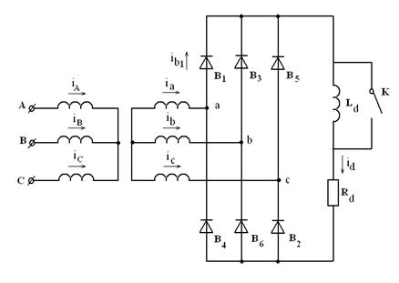
1.1.5 Larionov’s scheme
A
three-phased bridge rectifier (Larionov’s scheme) finds widespread application
in transformational technique. In this scheme three valves are united in cathode
group and another three valves -in anode one. During the work of such a scheme
current is always conducted by two valves: one in cathode group, another is
anode group. At any time moment in cathode group there will be opened that
valve, anode potential of which is higher that anode potentials of other valves
in group- a valve, cathode potential of which is lower that cathode potentials
of other valves group. Commutation of current from one valve to the regular
one, next in given group, occurs in moments of sinusoids’ cross-section of
secondary winding transformer phase voltages. Valves of scheme conduct current
during  of period.
Sequence of introduction in work of valves corresponds to their numbers (look
figure of three - phased bridge scheme on active-inductive load). As a result
potential of total scheme cathodes (positive pole of rectifier) is changed over
upper skirter of phase voltage curves, and potential of total anode (negative
pole of rectifier)- over lover skirter. Rectified voltage Ud is
equal to the potential difference of positive and negative rectifier’ poles.
The voltage on valve is defined as difference of its cathode and anode
potentials.
of period.
Sequence of introduction in work of valves corresponds to their numbers (look
figure of three - phased bridge scheme on active-inductive load). As a result
potential of total scheme cathodes (positive pole of rectifier) is changed over
upper skirter of phase voltage curves, and potential of total anode (negative
pole of rectifier)- over lover skirter. Rectified voltage Ud is
equal to the potential difference of positive and negative rectifier’ poles.
The voltage on valve is defined as difference of its cathode and anode
potentials.
 1.6 - The three - phased bridge
scheme on the unregulated valves.
1.6 - The three - phased bridge
scheme on the unregulated valves.
Mainly in bridge rectifier there’s
no forced magnetization of transformer core because current in secondary
winding flows twice a period, in opposite directions. In three - phased current
rectifiers for decreasing of rectified current alternative component there
usually link up inductive smoothing filter successively with a load, inductance
of which has definite value.
Nowadays when force semi-conductor
valves are used mostly, Larionov’s scheme has got wide application because of
its well technico-economic indicies: effective usage of transformer, low value
of inverse voltage on valve, comparently low coefficient of pulsation, high
coefficient of useful action and others. It should be mentioned that for
Larionov’s scheme all electric parametres are calculated when mn=6.
1.2 The review of constructive
solutions
is a device which is intended for
transformation of alternative voltage into direct one. The main elements of
rectifier are transformer and valves, with aid of which there’s provided
one-sided current flowing in load circuit, as a result alternative voltage is
transformed into pulse one. For regulation and stabilization of rectified
voltage and current of consumer regulator of stabilizator is linked up to its
enternal terminals. According to phase number of power supply voltage there are
schemes of one - phased and three - phased rectification.
The main magnitudes which
characterise the operational properties of rectifiers:
- average value of rectified
voltage and current (Uav, Iav);
- efficiency
(η);
- power
coefficient (χ);
- external
characteristic - dependence of voltage on exit from load current  ;
;
regulation
characteristic - dependence of rectified voltage from regulation angle  ;
;
pulsation
coefficient - relationship of amplitude of given rectified voltage (current)
harmonic component to the average value of rectified voltage (current)  . (1.1)
Schemes of three - phased current
rectifiers are applied generally for power supply of middle and great power
consumer. They informly load a network with three - phased current and are
differed due to high coefficient of transformer usage. Such schemes are used
for power supply of static load with opposite EMF (electrolise and other), and
also dynamic load is form electroengines of direct current.
1.3 Statement of problem
It is necessary to calculate and
design the rectifier with active-inductive load Is Given:d - an
average rectified voltage, Ud = 100 V;d - an average
rectified current, Id =7 A;1 - a voltage of a three -
phased supplied network, U1 =127 V;c - frequency of a
supplied network, fc =50 Hz.is necessary to do:
choose the rectifier scheme;
execute calculation;
realize selection of elements for
device;
design the construction of device;
to do the assembly drawing and
drawing of the printed circuit card. a base I choose a three-phased bridge
rectifier scheme (Larionov’s scheme figure 1.6).
2. PRINCIPLE OF DESIGNED SCHEME
OPERATION
’s consider a three-phased bridge
rectifier (Larionov’s scheme figure 1.6).
Two three-phase rectifer groups
connected in series in scheme: anode D2,D4,D6 and cathode
D1,D3,D5 , each of one repeats work of three-phased rectifier with center tap.
So this scheme has average rectifiered voltage Uav in two times greater, at the
same EMF value of secondary transformer winding E2 , as in the three-phase
rectifier with a center tap.the bridge sheme two valves pass through current:
one - with more higher anode potential relativly to zero point of the
transformer from valve cathode group; and another - with more lower cathode
potential from valve anode group.voltage has six-phase
pulsations, thought the period of work of each
valve remains the same as in three-phase scheme with center tap. There is no
forced core magnetization
of transformer in bridge rectifier, as current flows twice over a period in
secondary winding,in opposite directions.
Larionov’s scheme got wide
application as a result of its good technical and economic indices: effective
transformer using, small value of inverse voltage on the valve, comparatively
small pulsation coefficient, high efficiency factor and other.
3. CALCULATION OF RECTIFIER WORKING
ON ACTIVE-INDUCTIVE LOAD
DATA:d - an average
rectified voltage, Ud = 100 V;d - an average rectified
current, Id =7 A;1 - a voltage of a three - phased
supplied network, U1 =127 V;c - frequency of a supplied
network, fc =50 Hz.
1. On the basis of rectified
current and voltage values and also for decreasing the transformer dimensions
and filter dimensions, decreasing of consumed from the network power, let’s
choose Larionov’s scheme with star-star winding connection.
2. From the table 19.2 [6]
let’s define:
 V (4.1)
 A (4.2)
3. The active resistance of
transformer phase:
 (4.3)
(4.3)
where value
Kr is taken from the table 19.3 [6] in case of inductive load,
consequently Kr =2,5.
4. Inductance of transformer
winding dispersion:
 (4.4)
(4.4)
where value
KL is taken from table 19.3 [6] in case of inductive load, 
5. Voltage drop on the valves
in the scheme
 V. (4.5)
6. Idling voltage with counting
of rectifier phase resistance rtr
and voltage drop on throttle ΔUth:
 (4.6)
(4.6)
where ΔUth
=(0,1…0,05)Ud for Pav =(100…1000)Wt,
av
=Id Ud =7 100=700 Wt. (4.7)
. The
precise value of inverse voltage on a valve:
 (4.8)
(4.8)
8. According
to the table 19.2 let’s define parameters of the transformer
 (4.9)
(4.9)
 (4.10)
 (4.11)
 (4.12)
 (4.13)
9.Angle of
commutation:
 (4.14)
Consequently
γ=arcos 0,991 =80
10. Minimum available inductance
of filter throttle:
 (4.15)
11. The external characteristic
of rectifier present a straight line, which is constructed by two points: Id
=0; Ud =Uavi (idling) and Id, Ud
(nominal load).
12. Inner resistance of
rectifier:
 (4.16)
Efficiency:
 (4.17)
 (4.18)
 (4.19)

14.
Calculations of geometrical sizes of the wires
For definition of a sectional area
of the current carrying wire, radiating from value of a current and an economic
current density (for conductors from copper J = 0,9~1,2 А/mm2,
from aluminum J = 0,7~0,9 А/mm2) it is used the following
formula:
 (4.20)
where q1
- the cross-section of a conductor, mm2; I1
- the greatest working current of a conductor, And; J - the accepted
current density, А/mm2.
For accounts it is chosen economic
current density J = 0,9 А/mm2 (copper), the greatest working
current I1 = 2,31 A.

Sectional area q1
= 2,57 mm2.
Radiating from the obtained cut,
under the gage the wire or the tire of equal or proximal cut is selected. The
material of a winding (aluminum or copper) is selected on constructive and
economic reasons. The diameter of the tire is equal:
 (4.21)
the diameter
of the tire is equal d = 1,8 mm. According to the catalogue the rated
diameter up to d = 2 mm.
4.
CONSTRUCTION OF THE DEVICE
three-phase
rectifier scheme is relevant to uncontrollable three-phase current rectifiers
schemes.They are used for consumer supplying of middle and high power.They are
uniformly loading three-phase power circuit and have high use factor of
transformer.
By calculated values we choose
diods,throlle, plug and transformer.rinted circuit card
dimensions
are 140´175
mm, width
3 mm,
general-purpose glass-cloth laminate material uninflammable filtered СОНФ-2
(ДСТУ 12652-74), filtering width
50 мкм. Mass
of card nearby
0,4 kg.
Elements
are soldered
ПОС61 ДСТУ 21931-76. of assembling
- printed, hard.
Bracing of
elements
is hinged,plug
is connected
by flexible bonding
wire with isolution
fritted from froth
(ТУ 16-505.083-78).All elements of the printed
card are connected by copper wire with diameter 2mm. Card may situated on slide
rails.
CONCLUSION
The results of the given course
design became constructed and calculated at a three - phase rectifier working
on active-inductive load. A design of a rectifier - unitized. The given device
has both virtues and a limitation.
Rectifier is such a device that is
intended for transformation of alternative voltage into direct one. The main
elements of rectifier are transformer and valves, with aid of which there’s
provided one-sided current flowing in load circuit, consequently alternative
voltage is transformed into pulse one.
Taking into account the initial data
and calculated value of the given rectifier I chose the three-phase bridge
rectifier (Larionov’s scheme) with star-star winding connection. Generally,
schemes of three-phase current rectifiers are applied mostly for power supply
of middle and great power consumers. They uniformly load a network with
three-phase current and are differed due to high coefficient of transformer
usage. Such schemes are used for power supply of static load of active and active-inductive
character, static load with opposite EMF and others.should be mentioned that
nowadays when force semi-conductor valves are used mostly, Larionov’s scheme
has got wide application because of its well technico-economic indicies:
effective usage of transformer, low value of inverse voltage on valve,
comparently low coefficient of pulsation, high efficiency and others. In
three-phased current rectifiers for decreasing of rectified current alternative
component there usually link up inductive smoothing filter in a series with
load, inductance of which has definite value (LH).
Mainly in bridge rectifier there’s no forced magnetization of transformer core
because current in secondary winding flows twice a period, in opposite
directions.
LIST OF THE LITERATURE
1. Варламов
Р.Г. Компоновка радиоэлектронной аппаратуры. - М.: Советское радио, 1975.-352с.
2. Справочник
конструктора РЭА / Под ред. Варламова Р.Г. - М.: Радио и связь, 1985.-354с.
3. Лярский
В.Ф., Мурадян О.Б. Электрические соединители: Справочник. - М.: Радио и связь,
1988.-272с.
4. Электрические
кабели и провода, шнуры: Справочник / Под ред. Белоруссова И.И. - М.:
Энергоатомиздат, 1987.-536с.
5. Сидоров
Н.Н. и др. Малогабаритные трансформаторы и дроссели: Справочник. - М.: Радио и
связь, 1985.-540с.
6. Исаков
Ю.А. и др. Основы промышленной электроники. - К.: Техника, 1976.-554с.
7. Усатенко
С.Т. и др. Выполнение электрических схем по ЕСКД: Справочник. - М.:
издательство стандартов, 1989.-325с.
8. Диоды:
Справочник / Под ред. Григорьева О.П. и др. - М.: Радио и связь, 1990.-335с.
9. Полупроводниковые
приборы. Диоды выпрямительные, стабилитроны, тиристоры: Справочник / Под ред.
Голомедова А.В. - М.: Радио и связь, 1983.-523с.
10.Янковенко
В.С. и др. Расчет и конструирование элементов электропривода. - М.:
Энергоатомиздат, 1987.-320с.
11.
APPENDIX A
Reference data of diodsto the
calculated values of Uinv max =92V and Id=2,31A I have
chosen in quality of valves the silicic diods of type KD202Г.
The
main parameters of the diod type KD202Г:
- maximum available constant
(average) direct current =3,5A;
- maximum available constant
inverse voltage =100V;
constant inverse current
=0,8 mA;
constant (or average)
voltage=0,9 B;
enviroment temperature
rate: -60 - +30 o ’s depict the construction of this diod:
APPENDIX B
Reference
data of throttle.to the calculated value of minimum available inductance of
filter throttle Lth min=0,4*10-3Gn and magnetization
current I=3,2A I have chosen the throttle of type D201T.main parameters of this
throttle:
typedimension
of magnetowire ШЛ
5х5;
mass is
equal to 40g.’s depict the construction of the given throttle:
 B - The throttle of the type D201T
The dimensions of the throttle are
the following:=12mm=25mm=14mm=27,5mm=4mm=29mm=M2,5
APPENDIX C
Reference data of transformer.to the
given data and calculations I chose the transformer of type ТПП
273-127/220-50. Electrical parameters of the transformer are: = 220V - voltage
on the primary winding= 127V - voltage on the secondary winding
I= 12A - output current
P= 960 Wt - power =50 Hz -
frequencydimensions:= 50 mm= 81 mm = 92 mm= 10 mm= 88 mm= M5
Figure C - Construction of the
transformer of the type ТПП
273-127/220-50
APPENDIX D
Reference data of
clamped connection
 D - Construction of the clamped
connection
D - Construction of the clamped
connection
connection of type Б-324-4
are intended for wire joining and branches in electrotechnical circuits (power,
management, signalizings, illuminations and others)of voltage 100 V and
frequency 50 Hz.