Traffic indicators investigation
Traffic indicators investigation
1. Theoretical
information
flight airspace flow
Control Zone - a controlled airspace extending upwards from the surface of the
earth to a specified upper limit, control and ATS of which is provided by
appropriate ATS unit.
Terminal Control
Area - a control area
normally established at the confluence of ATS routes in the vicinity of one or
more major aerodromes.main purpose of TMAs is the provision of safe flights for
aircraft leaving system of ATS routes for landing at given airdrome or
taking-off from the airdrome and entering the ATS routes system.required TMA dimensions
are determined by provision of
descend and landing approach conditions via the shortest way (straight-in
approach) for aircraft, which passed entrance corridor at the upper established
flight level for TMA till the transition level and moment of reaching CTR
borders, taking into account aircraft performance characteristics for aircraft
operating at this airdrome.in approach pattern is considered like the most
economical and provides the TMA capacity almost corresponding to norm, but
requires greater TMA dimensions.of TMA radius is performed according to
formulas:
ТМА ³
дmax + Slate + Sdes + SCTR/2;
Slate = MC* (twl + treact);des = MCS*(Hent - HGPE)/vy,where:
дmax - error of determination by the crew of moment of flight over outer
marker (the border of TMA);late - distance, of flight of aircraft from the moment of flight of outer
marker to the moment of beginning of descent;
Sdes - distance of flight of the aircraft at the descending from Нent to НGPE;CTR - size of CTR from side of approach;
MC - true air speed of flight of the aircraft at the entrance in
aerodrome zone;
twl - average time of
occupancy of ATCo by a radio exchange with other crew;react - ATS
system delay;
Нent -
altitude (flight level) of entrance in aerodrome zone;
НGPE - glide slope entrance height;- forward speed of an aircraft at the descending from НВХ to НВГ;y - rate of descent of an aircraft from Нent to НGPE
ATS route - certain route assigned for directing traffic flow with the aim
of ATS provision. This term is used for airways, controlled or uncontrolled
routes, conditional routes, arrival and departure routes etc.
Airway - an airspace corridor with limited height and width and equipped
with ground based navigation aids.
Air corridor - connection between ATS routes and control zone.
Types of air
corridors:
· arrival (approach) to the aerodrome area;
· departure from the aerodrome area;
· mixed (arrival, departure).
Air Traffic - all aircraft at flight or moving in aerodrome manoeuvring zone.
Separation - intervals between aircraft, levels or tracks.
Flight Level - a surface of constant atmospheric pressure which is related to
a specific pressure datum, 1 013.2 hectopascals (hPa), and is separated from
other such surfaces by specific pressure intervals.1. A pressure type altimeter
calibrated in accordance with the standard atmosphere:
1. when set to a QNH
altimeter setting, will indicate altitude;
2. when set to a
QFE altimeter setting, will indicate height above the QFE reference datum;
. when set to a
pressure 1 013.2 hPa, may be used to indicate flight levels.2. The terms
«height» and «altitude», used in Note 1 above, indicate altimetric rather than
geometric heights and altitudes.
When we set QFE pressure
it will show us a relative height over the aabutment point of QFE;we set
pressure 760mm (1013,2 Hpa) it may be used for indication of flight levels;
Air traffic
management - is a complex of
ground and onboard facilities, that are necessary for provision of safety of
flight during all its steps.
Air traffic service
- flight information
service, consultative service, emergency service, air traffic control service
(approach air traffic control service, terminal air traffic control service,
area air traffic control service)
Intensity of flight
- amount of aircraft
actually taken to a control.


 - amount of aircraft;-
average time of flight of aircraft in air traffic area;
- amount of aircraft;-
average time of flight of aircraft in air traffic area;
Density
of air traffic - amount of aircraft, that
are in 1 unit of volume of air traffic control zone.
 ;
;  ;
;
Load
of zone - amount of aircraft that are under control in the limits of given
zone simultaneously.

Coefficient of load
of zone:

 - throughput.
Throughput
of air traffic zone - amount of aircraft that
can be serviced by air traffic control units of this zone in 1 unit of time
with adherence of normative indications of safety of flights.
Throughput
of air traffic controller - amount of aircraft that
can be under control of air traffic controller in 1 unit of time taking into
account direct procedures of control simultaneously.
Work
load of air traffic controller - time needed to
perform necessary technological procedures of air traffic control.
Factors
that influence on commitment:
intensity
of flights;
density
of flights;
structure
of zone (size, amount of routes, amount of points of intersection of routes)
characteristics
of aircraft flows (directions of flows, relations of types of aircraft in
flows) equipment of work place
air
traffic management (features of work technology, amount of air traffic
controllers in 1 zone, character of restrictions in airspace)
level
of air traffic controller
work
place management
regim
of work and rest
character
of work place environment
psychological
and psycho-physical characteristics of air traffic controller
Coefficient
of work load of air traffic controller is
expressed by relation of time spent by air traffic controller to perform
technological procedures and total resource of time.

 - is obtained only when
we can calculate the time of operations.
Coefficient of work load of air traffic controller has to be placed in the limits ftom 0.2 to 0.85, normative
coefficient is 0.55. Relation
between commitment coefficient and main characteristics of flow of aircraft is
expressed by following equation:
- is obtained only when
we can calculate the time of operations.
Coefficient of work load of air traffic controller has to be placed in the limits ftom 0.2 to 0.85, normative
coefficient is 0.55. Relation
between commitment coefficient and main characteristics of flow of aircraft is
expressed by following equation:

 - time spent on voice
communication during aircraft aperations (ex.: climbing, descending)
- time spent on voice
communication during aircraft aperations (ex.: climbing, descending)

 - time spent on giving
of instructions to change FL, direction of flight, conflict situation,
conditions of flight.
- time spent on giving
of instructions to change FL, direction of flight, conflict situation,
conditions of flight.

 - time spent on
information exchange between neighbour controllers, air traffic coordination,
work with strips and equipment of air traffic control system.
- time spent on
information exchange between neighbour controllers, air traffic coordination,
work with strips and equipment of air traffic control system.

2. Calculation
of TMA sizes
|
Manufactured type and modification
|
Speed
|
ROC
|
|
MC
|
MCS
|
AS
|
|
|
Boeing 767 - 300
|
895
|
405
|
260
|
18/8
|
|
Airbus 320
|
895
|
405
|
260
|
17/10
|
|
Fokker 100
|
840
|
370
|
260
|
7/4
|
|
IL-76
|
810
|
370
|
275
|
7/3
|
|
Yak 40
|
550
|
330
|
230
|
5/2
|
|
TMA 1 FL80 (2450m): RTMA ³ 4 +
6.5 + 36 + 19 ≈ 66 km; Slate =
248.6*(12 + 14) = 6.5 km; Sdes = 88.5*(2450 - 400)/5 = 36 km; Vdes= SCTR/2 = 19 km; дmax = 4
km; SCTR/2 = 19 km; дmax = 4
km;
|
TMA 2 FL180 (5500m): RTMA ³ 4 + 6.5 + 90 + 21≈ 122 km; Slate = 248.6*(12 + 14) = 6.5 km; Sdes = 88.5*(5500 -
400)/5 = 90 km; Vdes= SCTR/2 = 21 km; дmax = 4
km;
|
. Construction
of zone and flight plan
|
№
|
Route of flight
|
Entrance time
|
Entrance FL
|
ACFT type
|
Registration number
|
|
TRANSIT
|
1
|
МЮ-СК
|
08:00
|
390
|
B763
|
62501
|
|
|
2
|
ОВ-НМ-СУ
|
08:03
|
250
|
YK40
|
62502
|
|
|
3
|
ЕМ-БЕ-СУ
|
08:13
|
350
|
IL76
|
62503
|
|
|
4
|
ВК-БЕ-СК
|
08:25
|
360
|
IL76
|
62504
|
|
|
5
|
ЕМ-ЛП-СК
|
08:25
|
320
|
F100
|
62505
|
|
|
6
|
МЮ-ЕМ
|
08:30
|
430
|
B763
|
62506
|
|
|
7
|
СК-БЕ-ВК
|
08:32
|
320
|
F100
|
62507
|
|
|
8
|
ТВ-РТ-СУ
|
08:32
|
350
|
IL76
|
62508
|
|
|
9
|
ЕМ-МЮ
|
08:33
|
260
|
YK40
|
62509
|
|
|
10
|
СУ-БЕ-СК
|
08:34
|
390
|
A320
|
62510
|
|
|
11
|
СУ-РТ-ТВ
|
08:36
|
400
|
A320
|
62511
|
|
|
12
|
СК-МЮ
|
08:40
|
240
|
YK40
|
62512
|
|
|
13
|
ЕМ-БЕ-СУ
|
08:43
|
380
|
A320
|
62513
|
|
|
14
|
СК-БЕ-ВК
|
08:45
|
330
|
F100
|
62514
|
|
|
15
|
СК-ЕМ-ОВ
|
08:48
|
390
|
B763
|
62515
|
|
|
16
|
ОВ-ВК
|
08:50
|
240
|
F100
|
62516
|
|
|
17
|
МЮ-ЕМ
|
08:52
|
370
|
IL76
|
62517
|
|
|
18
|
МЮ-РТ-ЛП-ЕМ
|
08:55
|
330
|
F100
|
62518
|
|
|
19
|
СУ-НМ-ОВ
|
08:55
|
390
|
A320
|
62519
|
|
|
20
|
ЕМ-БЕ-СУ
|
08:59
|
400
|
B763
|
62520
|
|
TMA1 arrival
|
21
|
ВК-НМ-ДО
|
08:01
|
220/80/0
|
A320
|
32801
|
|
|
22
|
МЮ-БЕ-ДО
|
08:11
|
390/70/0
|
B763
|
32802
|
|
|
23
|
ОВ-НМ-ДО
|
08:26
|
160/30/0
|
F100
|
32803
|
|
|
24
|
СУ-НМ-ДО
|
08:38
|
100/60/0
|
YK40
|
32804
|
|
|
25
|
ВК-НМ-ДО
|
08:57
|
300/70/0
|
IL76
|
32805
|
|
TMA1 departure
|
26
|
ДО-БЕ-МЮ
|
08:04
|
0/80/320
|
B763
|
51301
|
|
|
27
|
ДО-НМ-ВК
|
08:06
|
0/40/90
|
F100
|
51302
|
|
|
28
|
ДО-НМ-ОВ
|
08:28
|
0/80/270
|
IL76
|
51303
|
|
|
29
|
ДО-БЕ-ЕМ
|
08:29
|
0/70/210
|
YK40
|
51304
|
|
|
30
|
ДО-БЕ-МЮ
|
08:55
|
0/80/360
|
B763
|
51305
|
|
TMA2 arrival
|
31
|
ТВ-РТ-АР
|
08:02
|
330/120/0
|
B763
|
15101
|
|
|
32
|
МЮ-РТ-АР
|
08:15
|
230/90/0
|
F100
|
15102
|
|
|
33
|
ЕМ-ЛП-АР
|
08:31
|
320/130/0
|
A320
|
15103
|
|
|
34
|
СК-ЛП-АР
|
08:45
|
250/100/0
|
IL76
|
15104
|
|
|
35
|
МЮ-РТ-АР
|
08:53
|
200/70/0
|
F100
|
15105
|
|
TMA2 departure
|
36
|
АР-РТ-ТВ
|
08:05
|
0/90/200
|
YK40
|
14005
|
|
|
37
|
АР-ЛП-СК
|
08:07
|
0/90/160
|
F100
|
14001
|
|
|
38
|
АР-РТ-ТВ
|
08:22
|
0/110/320
|
B763
|
14002
|
|
|
39
|
АР-РТ-МЮ
|
08:36
|
0/130/300
|
B763
|
14003
|
|
|
40
|
АР-ЛП-ЕМ
|
08:48
|
0/120/350
|
14004
|
4. Modeling of zone in experimental program «Potok»
The experimental
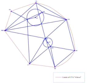
controlled airspace «Ivlieva» at program «Potok» looks like:
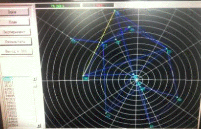
Fig.5.1 The look of CTA
«Ivlieva» in program «POTOK»
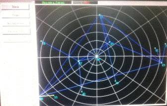
the experiment has been
made, 1 conflict situation occurred within the limits of CTA (fig.5.2).
 .5.2
The conflict situation
.5.2
The conflict situation
conflict situation has occurred in TMA1 zone on the segment БЕ-ДО. The horizontal
distance between ACFT at the moment of conflict was about 10.5 km. According to
nowadays standards, it is not the conflict because in TMA zone we use the 5NM
(9.3 km) separation minima. But as the program is old, the separation minimum
in its database equals 30 km. So, the following measures can be used to avoid
such conflict:
. Order one ACFT
to stop climb and another to stop descent until the creation of longitudinal
separation;
. To create
lateral interval by means of turning ACFT with less speed left or right on 30
degrees. After the creation of lateral interval to allow further climb or
descend, and after creation of VSM, return ACFT with less speed to the rout.
5. Analysis of
main flow direction of modeled airspace
flow direction:

Fig.6.1 Direction of
traffic flow
- 10% of flow has
direction 0°
2.5% of flow has
direction 30°
22.5% of flow has
direction 60°
5% of flow has direction
90°
2.5% of flow has
direction 120°
12.5% of flow has
direction 150°
7.5% of flow has
direction 180°
0% of flow has direction
210°
10% of flow has
direction 240°
10% of flow has
direction 270°
10% of flow has
direction 300°
7.5% of flow has
direction 330°to the flight levels:
FL 430 has main flow
direction 90°
FL 400 has main flow
direction which is divided 50/50 between 240° and 0°
FL 390 has main flow
direction 60°
FL 380 has main flow
direction 240°
FL 370 has main flow
direction 90°
FL 360 has main flow
direction 0°
FL 350 has main flow
direction 150°
FL 330 has main flow
direction 180°
FL 320 has main flow
direction 300°
FL 270 has main flow
direction 150°
FL 260 has main flow
direction 270°
FL 240 has main flow
direction which is divided 50/50 between 60° and 240°
FL 220 has main flow
direction 0°
FL 210 has main flow
direction 330°
FL 200 has main flow
direction 60°
FL 160 has main flow
direction 300°
FL 100 has main flow
direction 60°
FL 90 has main flow
direction 150°
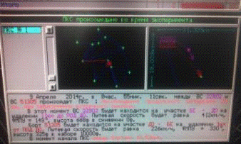
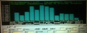
. Determination
of density and intensity of the flow
I have determined
density and intensity for 10 minutes intervals and constructed a histogram,
which contains information about density and intensity of traffic flow for
every 10 minutes of research (fig.7.1).
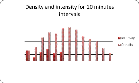
Fig.7.1 Density and
intensity for 10 minutes intervals
L route = 8500 kmat intervals:
- 00-10:
- 11-20:
- 21-30: 
- 31-40: 
- 41-50: 
- 51-60: 
- 61-70: 
- 71-80: 
- 81-90: 
- 91-100: 
- 101-110: 
- 111-120: 
- 121-130: 
The workload coefficient
calculated in «POTOK» is shown on figure 7.2.
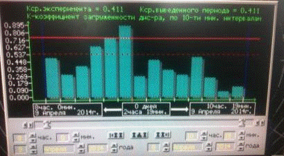 .7.2
The ATCO workload
.7.2
The ATCO workload
On the figure 7.2 there
is the ATCO workload coefficient for every 10 minutes. According to this
diagram:
- Average ATCO workload = 0.67;
- Min ATCO workload = 0.090;
- Max ATCO workload = 0.895.the analysis of results obtained above I
can make the conclusion that the ATCO is overloaded because there is a period
of time when the workload coefficient is greater than maximum acceptable.
That’s why I decided to divide CTA «Ivlieva» on two parts in horizontal plane
to decrease the workload of a controller.
7. Construction
of zone «Ivlieva_North», flight plan and ATCO workload
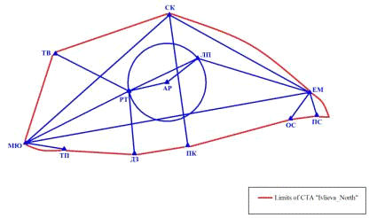
Fig.8.1 CTA
«Ivlieva_North» on scheme
8.1 Flight plan for CTA
«Ivlieva_North»
|
№
|
Route of flight
|
Entrance time
|
Entrance FL
|
ACFT type
|
Registration Number
|
|
TRANSIT
|
1
|
МЮ-СК
|
08:00
|
390
|
B763
|
62501
|
|
|
2
|
МЮ-ТП
|
08:11
|
390
|
B763
|
32802
|
|
|
3
|
ЕМ-ОС
|
08:13
|
350
|
IL76
|
62503
|
|
|
4
|
ЕМ-ЛП-СК
|
08:25
|
320
|
F100
|
62505
|
|
|
5
|
МЮ-ЕМ
|
08:30
|
430
|
B763
|
62506
|
|
|
6
|
СК-ПК
|
08:32
|
320
|
F100
|
62507
|
|
|
7
|
ТВ-РТ-ДЗ
|
08:32
|
350
|
IL76
|
62508
|
|
|
8
|
ЕМ-МЮ
|
08:33
|
260
|
YK40
|
62509
|
|
|
9
|
СК-МЮ
|
08:40
|
240
|
YK40
|
62512
|
|
|
10
|
ЕМ-ОС
|
08:43
|
380
|
A320
|
62513
|
|
|
11
|
СК-ПК
|
08:45
|
330
|
F100
|
62514
|
|
|
12
|
СК-ЕМ-ПС
|
08:48
|
390
|
B763
|
62515
|
|
|
13
|
МЮ-ЕМ
|
08:52
|
370
|
IL76
|
62517
|
|
|
14
|
МЮ-РТ-ЛП-ЕМ
|
08:55
|
330
|
F100
|
62518
|
|
|
15
|
ЕМ-ОС
|
08:59
|
400
|
B763
|
62520
|
|
|
16
|
ТП-МЮ
|
08:38
|
320
|
B763
|
51301
|
|
|
17
|
ДЗ-РТ-ТВ
|
09:07
|
400
|
A320
|
62511
|
|
|
18
|
ПК-СК
|
09:08
|
360
|
IL76
|
62504
|
|
|
19
|
ПК-СК
|
09:17
|
390
|
A320
|
62510
|
|
|
20
|
ТП-МЮ
|
09:29
|
360
|
B763
|
51305
|
|
TMA2 arrival
|
21
|
ТВ-РТ-АР
|
08:02
|
330/120/0
|
B763
|
15101
|
|
|
22
|
МЮ-РТ-АР
|
08:15
|
230/90/0
|
F100
|
15102
|
|
|
12
|
ЕМ-ЛП-АР
|
08:31
|
320/130/0
|
A320
|
15103
|
|
|
13
|
СК-ЛП-АР
|
08:45
|
250/100/0
|
IL76
|
15104
|
|
|
14
|
МЮ-РТ-АР
|
08:53
|
200/700/0
|
F100
|
15105
|
|
TMA2 departure
|
15
|
АР-ЛП-СК
|
08:07
|
0/90/160
|
F100
|
14001
|
|
|
16
|
АР-РТ-ТВ
|
08:22
|
0/110/320
|
B763
|
14002
|
|
|
17
|
АР-РТ-МЮ
|
08:36
|
0/130/300
|
B763
|
14003
|
|
|
18
|
АР-ЛП-ЕМ
|
08:48
|
0/120/350
|
B763
|
14004
|
|
|
19
|
АР-РТ-ТВ
|
08:05
|
0/90/200
|
YK40
|
14005
|
division of CTA lead to
the following:
 .8.2
The CTA «Ivlieva_North» in program «POTOK»
.8.2
The CTA «Ivlieva_North» in program «POTOK»
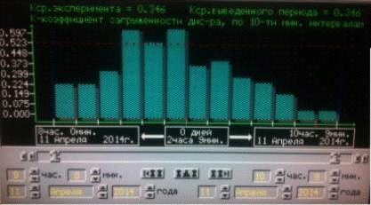
Fig.8.3 The ATCO
workload in CTA «Ivlieva_North»
Thus, according to the
obtained results we see that the ATCO workload fell down and remained
acceptable during the all period.
8. Construction
of zone «Ivlieva_North», flight plan and ATCO workload
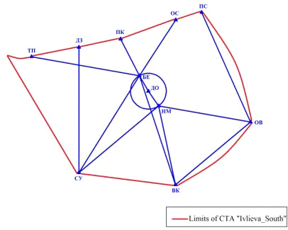
Fig. 9.1 CTA
«Ivlieva_South» on scheme
Table 9.1 Flight plan
for CTA «Ivlieva_South»
|
№
|
Route of flight
|
Entrance time
|
Entrance FL
|
ACFT type
|
Registration number
|
|
TRANSIT
|
1
|
ОВ-НМ-СУ
|
08:03
|
250
|
YK40
|
62502
|
|
|
2
|
ПК-БЕ-СУ
|
08:20
|
350
|
IL76
|
62503
|
|
|
3
|
ВК-БЕ-ПК
|
08:25
|
360
|
IL76
|
62504
|
|
|
4
|
ПК-БЕ-ВК
|
08:46
|
320
|
F100
|
62507
|
|
|
5
|
ОС-БЕ-СУ
|
08:49
|
380
|
A320
|
62513
|
|
|
6
|
СУ-БЕ-ПК
|
08:34
|
390
|
A320
|
62510
|
|
|
7
|
СУ-ДЗ
|
08:36
|
400
|
A320
|
62511
|
|
|
8
|
ОВ-ВК
|
08:50
|
240
|
F100
|
62516
|
|
|
9
|
СУ-НМ-ОВ
|
08:55
|
390
|
A320
|
62519
|
|
|
10
|
ОС-БЕ-СУ
|
09:05
|
400
|
B763
|
62520
|
|
|
11
|
ДЗ-СУ
|
09:06
|
350
|
IL76
|
62508
|
|
|
12
|
ПК-БЕ-ВК
|
09:14
|
330
|
F100
|
62514
|
|
|
13
|
ПС-ОВ
|
390
|
B763
|
62515
|
|
TMA2 arrival
|
14
|
ВК-НМ-ДО
|
08:01
|
220/80/0
|
A320
|
32801
|
|
|
15
|
ТП-БЕ-ДО
|
08:17
|
390/70/0
|
B763
|
32802
|
|
|
16
|
ОВ-НМ-ДО
|
08:26
|
160/30/0
|
F100
|
32803
|
|
|
17
|
СУ-НМ-ДО
|
08:38
|
100/60/0
|
YK40
|
32804
|
|
|
18
|
ВК-НМ-ДО
|
08:57
|
300/70/0
|
IL76
|
32805
|
|
TMA2 departure
|
19
|
ДО-БЕ-ТП
|
08:04
|
0/80/320
|
B763
|
51301
|
|
|
20
|
ДО-НМ-ВК
|
08:06
|
0/40/90
|
F100
|
51302
|
|
|
21
|
ДО-НМ-ОВ
|
08:28
|
0/80/270
|
IL76
|
51303
|
|
|
22
|
ДО-БЕ-ОС
|
08:29
|
0/70/210
|
YK40
|
51304
|
|
|
23
|
ДО-БЕ-ТП
|
08:55
|
0/80/360
|
B763
|
51305
|
«Ivlieva_South» has a
following look:
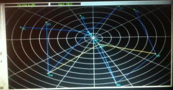
Fig.9.2 The look of CTA
«Ivlieva_South» in program «POTOK»
 .9.3
The ATCO workload in the CTA «Ivlieva_South»
.9.3
The ATCO workload in the CTA «Ivlieva_South»
We see that ATCO
workload fell down and became normal during the all period of time.
Conclusion
After the performance of
term work I analyzed obtained results and made the conclusion that the ATCO
workload depends on such traffic indicators as density, intensity, etc. That’s
why suitable planning of airspace structure leads to declining of workload which
reduces the possibility of conflicts and conflict situations appearance.
References
1. Terms of
aircraft operations and air traffic services in the classified airspace of
Ukraine: Order of the Ministry of Transport of Ukraine of 16.04.2003 №293 as
amended by the order of Ministry of Transport of Ukraine of 31.01.2004 p., №62.
(registered with the Ministry of Justice of Ukraine 23.02.2004, №238/8837) / /
Official Herald of Ukraine. - 2003. - №18.
. Doc 8643/37.
Aircraft type indicators: - 37th ed. - Montreal: ICAO, 2009.
. Doc 4444-ATM/501.
Air traffic management: - 15th ed. - Montreal: ICAO, 2007.