Stabilyty of Erth dam
Ministers
of education and since- Farabi Kazakh National Universityof Mechanics and
Mathematicsof Mechanics
Specialty: 5B060300
Mechanics
REPORTMANUFACTURING
PRACTICE ON THE TOPIC OF THE THESIS THEME:
stability of an earth dam
Student:
Ospanov N. Msupervisor : Alibayeva. K. A
Алматы 2015
COTENTS
INTRODUCTION
. STABILTY OF AN EARTH DAM
.1 Equipment Diagrams
.2 Equipmen setup
.3 Experiment results
INTRODUCTION
class of problems involving flow of water through permeable
media has a wide range and is of considerable importance to engineers and
scientists. The Armfield Drainage and Seepage Tank, Model S1, facilitates a
detailed study of the movement of water through permeable media.engineer is
probably the one who faces such problems most frequently and whose success or
failure will often depend on his knowledge and understanding of phenomena
related to the movement of the water in soils. This is one of the most important
aspects in the design of almost all hydraulic structures. Consider an earth or
rock fill dam, for instance. Water flows directly through the engineering
structure itself. Obviously, it is important to know how much water we can
expect to lose from the reservoir by seepage through the dam. We also need to
know whether a certainkind of soil can be used to construct the dam without
running the risk that the reservoir will run dry after filling. The safety and
the very existence of the dam edepends on the flow pattern of the penetrating
water and on the balance of the hydraulic and static forces. Many earth dams
have collapsed because of improper design with respect to the movement of water
through their bodies. In fact, the conditions of seepage are vital, not only
for earth dams, but for any dams having permeable materials in the foundations.
A dam can collapse or be badly damaged as a result of seepage underneath its
bottom, or because of hydrostatic forces exerted by the penetrating waters.
These forces cannot be determined without prior determination of the flow
pattern underneath the structure. Once known, they can be altered using drains,
cut-offs, sheet pile walls and other means to change the flow pattern.problems
arise in other engineering structures built from, or on, soil. As examples, we
can mention levees, road and railway embankments, canals, navigation locks,
foundations of buildings, bridges, harbour walls and similar structures
[1]engineering field where good understanding of water movement in soil is
essential is water supply and drainage. In both we are concerned with
extracting water from saturated strata by using wells, horizontal galleries,
tile lines, or trenches.this type of problem, we usually deal only with the
flow pattern and quantity of the water traversing the strata. The forces
exerted by seepage remain of secondary importance.[2]is an area where both
seepage and ground water flow is fundamentally important. The design of an
effective drainage system for a mine must be based on profound knowledge of
permeability, of the degree of water saturation of the various geological
layers, of seepage rates and of the effect of pumping or draining the water on
the balance of forces.water hydrology and hydrogeology are the main non-engineering
fields dealing with flow of water through permeable media and require the study
of problems such as salt water intrusion into fresh water basins, underground
movement of water towards inner channels, discharge of ground water into
surface run-offs, recharge of water from rivers to underground storage,
artificial recharge off all practical work areas and laboratories should be
covered by local safety. regulations which must be followed at all times. If
required Armfield can supply a typical set of standard laboratory safety
rules.Drainage and Seepage Tank has been designed to be safe in use, when
installed, operated and maintained in accordance with the instructions in this
manual.with any piece of sophisticated equipment, dangers may exist if the
equipment is misused, mishandled or badly maintained. If the equipment is used
in a manner not specified by Armfield then the protection provided by the
equipment may be impaired [3].S1 is a heavy piece of equipment, and should be
lifted fork lift if possible. Ensure that the arms of the fork lift do not foul
the sump moulding in the base of the unit. Do not attempt to lift the unit when
it is full of sand or water.
OBJECTIVE
continuing safety of an earth dam structure depends on the
stability of its slopes. The stability of the slope is in turn dependent on:
. the properties of the material of which the dam is
constructed;
. whether it is 'exposed' to water or air; and
. on conditions of seepage through the dam.experiment is to
demonstrate the process of collapse of an improperly designed earth dam with
slopes too steep for the material used. At the same time it may be noticed how
the water itself adjusts a dam's surface to the steepest slope allowable for
given conditions. This slope is called the critical slope.the laboratory, we
have the advantage of being able to use homogeneous materials of known
properties. This simplifies the problem and makes it possible to reduce the
number of components involved. By this means significant relationships between
the physical properties of the medium and characteristics of flow are found. To
further simplify the problem, we usually restrict ourselves to a
two-dimensional flow, investigating conditions in a vertical cross section*
along the horizontal direction of the moving water mass. The Armfield Drainage
and Seepage Tank, Model S1, is specifically designed to permit the simulation
in the laboratory of such vertical cross sections [4].
1. STABILTY OF AN EARTH DAM
.1 Equipment Diagrams
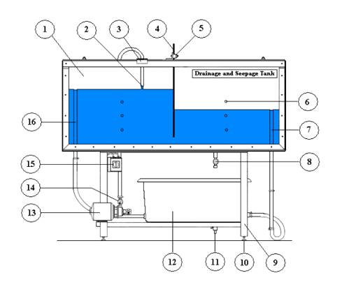
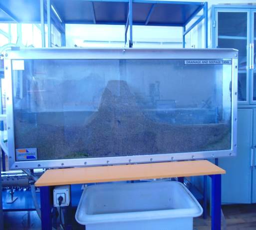
1.1: Front View of S1 Drainage and Seepage Tank (Shown with
impermeable baffle fitted but not filledn with sand)
)sand tank
) water inlet
) clamp
) impermeable baffle plate
) adjustable clamp
) incorporating six tapping points
) two independently adjustable overflows (7 & 16)
) A drain valve
) the frame
) adjustable feet
) sump tank drain
) sump tank
) centrifugal pump
) flow control valve
) electrical switch
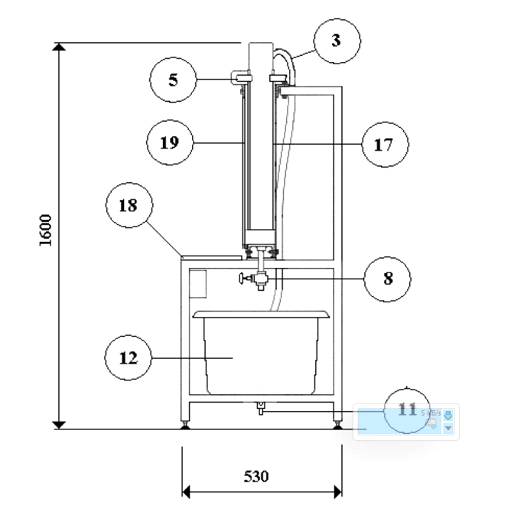 1.2: Side View of S1 Drainage and
Seepage Tank
1.2: Side View of S1 Drainage and
Seepage Tank
) aluminum back panel
) a shelf
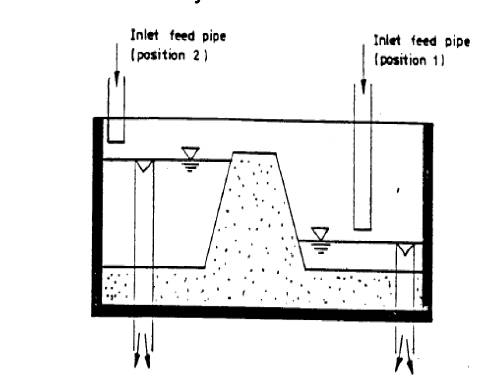
1.2 Equipment Set Up
dam water hydrodynamic stability
A segment of an earth dam is formed out of moist sand in the
middle of the tank with slopes as steep as the material permits.is poured into
the lower pool and, after it has reached the top of the overflow, the input is
transferred into the upper pool and maintained at a moderate rate 1.3 figure.
The rising water level in the upper pool will gradually undercut the upstream
slope of the dam and level it out into its "critical slope".the same
time the increasing rate of seepage will start washing away sandat the toe of
the downward slope, depositing them at a critical slope. It should be noticed
that the upstream and the downstream critical slopes are different, the
upstream slope being steeper.difference is due to the variant contributions to
stability of the hydrodynamic pressure of the penetrating water. Upstream the
water exerts pressure on the damand so contributes to its stability. Downstream
it acts to "pull" the sand moreor- less horizontally out of the
dam.process continues gradually until the upper part of the dam loses stability
and collapses. Then the whole process starts again and proceeds upwards to the
dam crest.
 1.3 Front view of the equipment set
up
1.3 Front view of the equipment set
up
1.3 Experiment results
) Water is poured into the lower pool as in figure 1.4
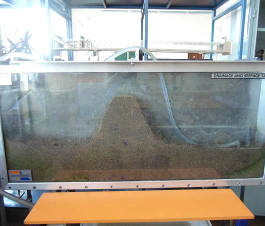
Figure 1.4 Front view of the equipment set up after water
poured in to the lower pool
2) The input is transferred into the upper pool and
maintained at a modern as in figure 1.5.
 1.5 The input is transferred into the
upper pool and maintained at a modern
1.5 The input is transferred into the
upper pool and maintained at a modern
) At the same time the increasing rate of seepage will start
washing away sand particles at the toe of the downward slope, depositing them
at a critical slope. It should be noticed that the upstream and the downstream
critical slopes are different, the upstream slope being steeper as in figure
1.6, 1.7.difference is due to the variant contributions to stability of the
hydrodynamic pressure of the penetrating water.
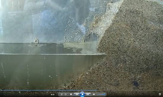 1.6 As we can see water start washing
away sand particles at the toe
1.6 As we can see water start washing
away sand particles at the toe
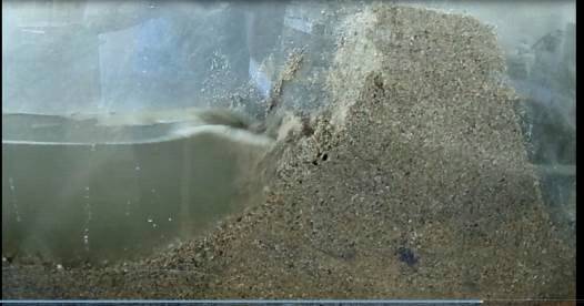 1.7 Top of the dam start collapsing
) Then, in the end upper part of the dam loses stability and
collapses as in figure 1.8.
 1.8 - Dam is colapsed, and stabiled
CONCLUSION
have seen the process of collapse of an improperly designed
earth dam with slopes too steep for the material used.I have noticed how the
water itself adjusts a dam's surface to the steepest slope allowable for given
conditions.I have learned how to find the critical slope.
REFERENCES
1.
S1 Issue 16 Instruction Manual
.
Flow of fluids throw porous materials R.Kolinz
. Шестаков
В.М. Динамика подземных вод